1 - Box construction
My goal is to keep the box size as small as possible. The estimates show that a box with about 50 liter internal volume would lead to acceptable amplifier power requirements. Keeping the box small also makes it easier to construct a very stiff enclosure and to minimizes spurious sound output from panel vibration.
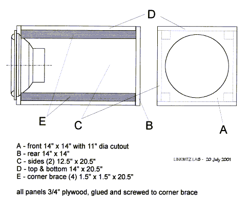
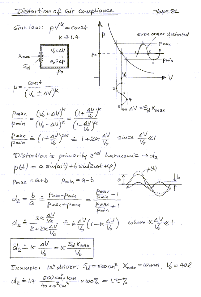
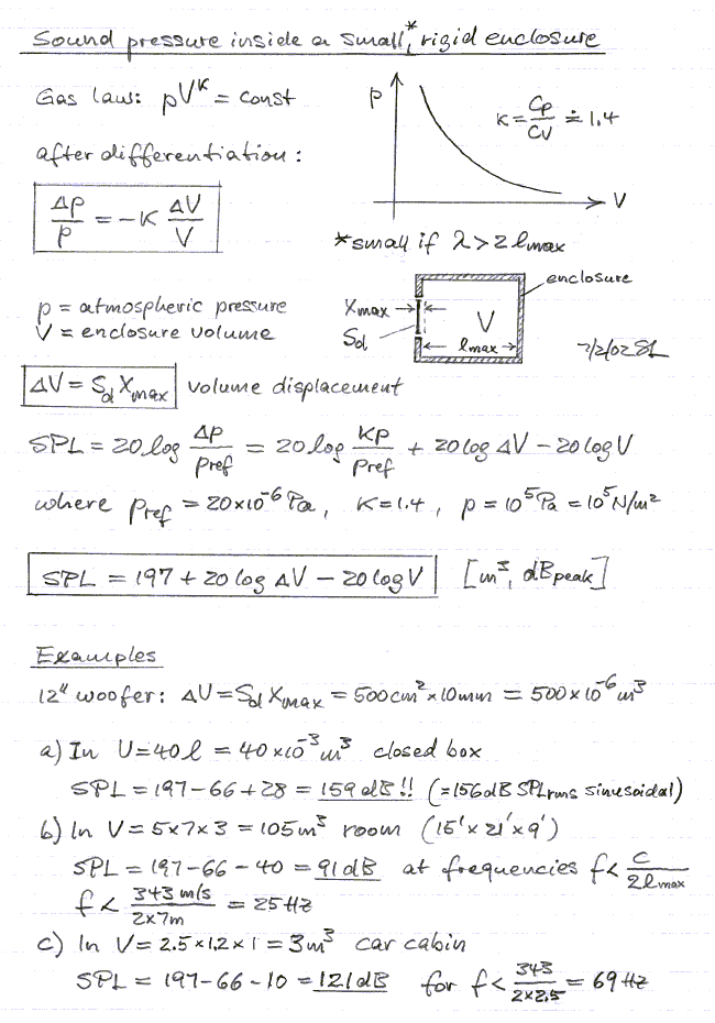
All joints are glued and strengthened with sheetrock screws. The driver is screwed to the front panel with a rubber gasket (neoprene weather stripping tape) under its flange. The box is completely sealed except for a small pin hole (<1 mm diameter) to equalize internal with external static pressure and to prevent displacing the cone from its normal resting position. No stuffing is used, to avoid nonlinear friction losses in case the material moves with cone displacement. The reduction in box resonance frequency that the stuffing could provide is not important, when the cut-off response is electronically controlled. The first internal air cavity resonance occurs when the 20.5" length equals 1/2 wavelength. This is at 330 Hz and far outside the frequency range of interest. The internal volume of the box is about 47 liter. The sound can get extremely high, but the additional of the inside air upon the cone is small compared to distortion of the driver motor.
I use four self-stick rubber feet on the bottom of the box to prevent damage of the wooden floor and to avoid rattle.
 此主题相关图片如下:
 此主题相关图片如下:
2 - Driver and box model
It would be quite feasible to build a subwoofer simply by mounting a chosen driver in a box of acceptable size and measure its frequency response outdoors with a microphone at 0.5" in front of the dust cap. From this information one could then design an equalizer to obtain the desired response curve.
It will be a more successful process, if you have some advance knowledge of what performance to expect from the driver and box combination and if you then measure the completed woofer to see if its response is as predicted. This requires a model. From the model you should also be able to predict the impedance that the amplifier sees, and the cone excursion for a given driving voltage, in order to calculate the power consumption as a function of frequency and SPL level. This allows decisions about driver selection and box size.
The electrical model uses the force --> current (velocity --> voltage) analogy between mechanical and electrical impedances. The conversion from acoustical impedances (p/q) to mechanical impedances (F/v), which involves Sd, and the conversion from mechanical to electrical impedances (V/I), with the use of Bl, is described in books on electro-acoustics. The electrical impedance model looks like the following circuit with component values derived from the XLS 830500 driver specifications and a 47 liter box. See closed-box1.xls for calculation of the values.
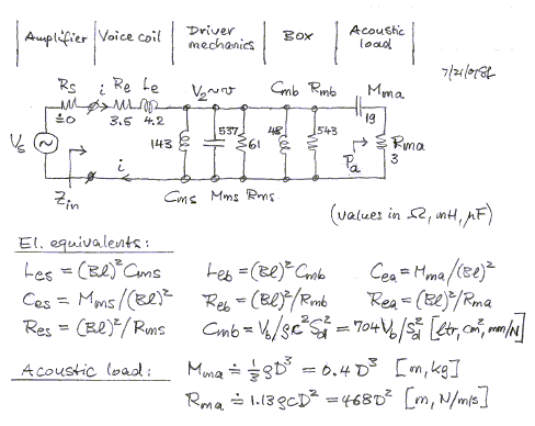
The circuit can be simplified by combining the two parallel inductors that represent driver and box compliance, and by combining the resistors for the viscous losses in driver and box. The reactance due to Le can be neglected at low frequencies compared to Re. Also, the power amplifier output resistance and speaker cable resistance Rs is insignificant when compared to Re. The reactive component Mma of the complex acoustic radiation impedance is very small compared to the moving mass Mms of the driver. Also, the corresponding capacitive reactance is much larger than the radiation resistance Ra. Thus, both will be ignored. It is worth noting that the electrical power dissipated in Ra is the same as the acoustic power radiated for a given amplifier voltage Vs. From the radiated power it is easy to determine the sound pressure at some distance in free-space, via sound intensity and free-space impedance. The sound pressure can also be derived from the cone velocity v, which is proportional to the voltage V2. The circuit behavior is most conveniently analyzed with a program like CircuitMaker .
The above model is thus simplified to the following:
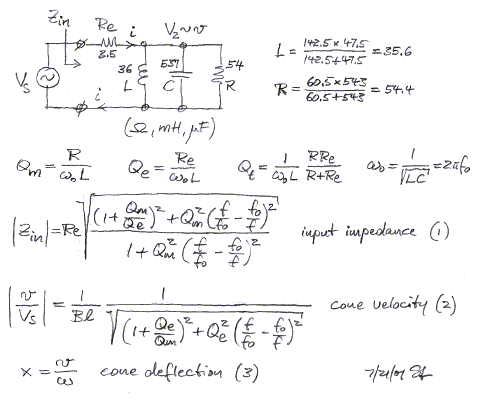
The derivation of formulas (1) and (2) from the circuit diagram takes a little effort using complex number algebra. At resonance, f = f0, the circuit simplifies to two resistors, Re and R, which allows to determine the relationship between voltage V2 and velocity v. All these quantities are calculated in a spreadsheet. The derivations above are mainly given for a better understanding of the inner workings of the spreadsheet and of the use and limits for the model.
3 - Spreadsheet results
The purpose of the closed-box1.xls spreadsheet is to study the power requirements of a particular driver in a box of specified size. It is assumed that the driver has adequate cone excursion capability to provide the desired sound pressure level at the lowest frequency of its intended operating range. The maximally obtainable SPL can be determined from the spreadsheet spl_max1.xls , but is also calculated by 'closed-box1'. The different parts of the spreadsheet will be referred to by their page tabs [...], which are at the bottom of the closed-box1.xls display. Click on them.
Install the Excel 97/2000 Viewer on your computer, if you do not have access to the Microsoft Excel spreadsheet program.
[Spec's] - Block 1 has the specifications of the XLS 830500. You can enter different driver parameters, but only change the bold faced numbers. Changing any other numbers will erase the underlying formulas. Note that if you enter VAS it will calculate Cms, in case this specification is not available.
Block 2 has the box data. The box Qb is set to a high value since there is no stuffing.
Block 3 gives the calculated driver parameters when mounted in the box.
Block 4 gives the values for electrical components of the simplified driver and box model.
The target response specification in block 5 will be need later to determine the necessary equalization together with the pole and zero locations that have been calculated for the model in 3a, 3b and the equalizer in block 6.
The results of the calculations are best observed in graphical format.
[Vp & Ip] - The curves show the required peak current and peak voltage from the power amplifier to obtain Xmax at different frequencies. The current has a minimum at the driver resonance. At low frequencies the amplifier is likely to run into current clipping before Xmax is reached. Reduce Vb to 23 liter, such as when a second driver is added at the other end of the box above, and you see how the current of each driver increases to unrealistic values. At frequencies above resonance the amplifier is likely to clip at its supply voltage. If the driver had a less strong motor with Bl = 10 N/A, then again the current demand on the amplifier would limit the maximum obtainable cone excursion.
[Power & SPL] - The SPL at 1 m increases at 12 dB/oct rate for constant excursion Xmax. Free-space is assumed. See Estimates
for SPL in a room. Three power curves are shown. The middle one is the product of rms current and rms voltage in VA. The other two power curves show the 8 ohm power rating that an amplifier would have to have, in order to deliver the required peak current or peak voltage, that are necessary to reach Xmax. It is clear that Xmax is difficult to reach above the resonance frequency with typical amplifiers. Since the SPl is already high at these frequencies there is no need for such large excursions.
[SPL @ 2.83 V] - The graph shows the SPL frequency response of the driver mounted in the box for a constant drive voltage of 2.83 V, which would correspond to 1 W into 8 ohm. The actual amplifier load impedance differs completely from 8 ohm, but that is no problem for any well designed solid-state amplifier. The only limits are the amplifier's output current capability and maximum output voltage swing. The response shows a broad roll-off, as would be expected from the low Qt = 0.4. The woofer obviously needs equalization to be useful. If you enter Bl = 10 N/A for the driver, then the response shows the more typical highpass behavior, but the voltage sensitivity is reduced since the motor has less strength.
[SPL & Ip @ 10Vp] - Knowing a power amplifier's maximum output current and voltage swing this graph allows to estimate the maximum SPL that can be obtained when using it. The SPL can, of course, not exceed the excursion limited SPL from the [Vp & Ip] tab.
For example, a LM3886 power IC with Vp = 30V and Ip = 11.5A would give a voltage limited SPL that is 20 log(30V/10V) = 9.5 dB higher than shown and require 3 times the current indicated in the graph. This would be within the specifications of the LM3886, but whether 95.5 dB free-space SPL at 1 m and 40 Hz is sufficient, depends upon the application. Bridging two devices will double the voltage swing capability, but now has insufficient peak output current, unless two ICs are connected in parallel. Such parallel/bridged arrangement of ICs has to be carefully designed, to distribute the current drawn uniformly between the four devices.
[Max SPL @ Vpeak] - The power amplifier to be used can be specified in Block 7 and the available peak voltage is calculated. For this peak voltage the maximally obtainable SPL is plotted. Typically, at low frequencies the SPL is excursion limited and Vpeak exceeds what is necessary. At higher frequencies the SPL becomes voltage limited, provided that the amplifier is capable of delivering the necessary peak current.
If the same driver is used in an open baffle with path length D to form a dipole radiator, then the maximally obtainable SPL is determined from Fequal in Block 8. Be sure to set the internal box volume in Block 2 to a value much larger than the driver's VAS.
[Impedance] - The impedance of the driver by itself and in the box. When the calculated box impedance is compared to an actual measurement, one can get an idea of the box losses and of Qb.
The remaining two tabs, [Test] and [EQ], are discussed on the following pages.


 加好友
加好友  发短信
发短信

 Post By:2006-11-3 9:38:24 [只看该作者]


 加好友
加好友  发短信
发短信

 Post By:2006-11-3 16:55:20 [只看该作者]


 加好友
加好友  发短信
发短信

 Post By:2006-11-8 20:23:12 [只看该作者]


 加好友
加好友  发短信
发短信

 Post By:2006-11-9 8:45:12 [只看该作者]


 加好友
加好友  发短信
发短信

 Post By:2006-11-10 21:20:10 [只看该作者]


 加好友
加好友  发短信
发短信

 Post By:2006-11-11 9:33:35 [只看该作者]


 加好友
加好友  发短信
发短信

 Post By:2006-11-11 16:59:49 [只看该作者]


 加好友
加好友  发短信
发短信

 Post By:2006-11-13 20:59:47 [只看该作者]


 加好友
加好友  发短信
发短信

 Post By:2006-11-13 21:49:19 [只看该作者]


 加好友
加好友  发短信
发短信

 Post By:2006-11-15 12:04:07 [只看该作者]


 加好友
加好友  发短信
发短信

 Post By:2006-11-15 16:26:12 [只看该作者]


 加好友
加好友  发短信
发短信
 小马哥
小马哥
 Post By:2006-11-15 16:44:56 [只看该作者]


 加好友
加好友  发短信
发短信

 Post By:2006-11-15 20:40:21 [只看该作者]


 加好友
加好友  发短信
发短信

 Post By:2006-11-16 10:14:32 [只看该作者]


 加好友
加好友  发短信
发短信

 Post By:2006-12-25 17:16:28 [只看该作者]


 加好友
加好友  发短信
发短信

 Post By:2006-12-25 17:39:10 [只看该作者]


 加好友
加好友  发短信
发短信
 陶醉
陶醉
 Post By:2007-1-21 15:03:31 [只看该作者]


 加好友
加好友  发短信
发短信

 Post By:2007-3-18 17:03:37 [只看该作者]


 加好友
加好友  发短信
发短信

 Post By:2007-4-13 10:37:19 [只看该作者]


 加好友
加好友  发短信
发短信

 Post By:2007-4-14 12:02:07 [只看该作者]
